Early Bridge Building
It is unclear whether catenary theory was understood by the early master masons, but the concept may have been known of in China . In Europe, early-medieval writing was in Latin and largely the preserve of clerics who seldom had an interest in engineering. We do know there was a ‘scientia’, or a body of knowledge, in Gothic times and later. Certainly, Gothic and early Renaissance architects applied principles of geometrical equilibrium. There were strict prescriptions of proportion, and occasionally some formulae empirically recommending maximum ratio sizes for arches, pier width and foundations. Proportions such as these may be the essence of very ancient masonic secrets. Palladio (Venice c.1560) and Serlio (Bologna c.1540) both recorded the average arch thickness and span of the Roman antiquities. The most prolific author and architect was Leon Battista Alberti (Genoa c.1450). His De Re Aedificatoria was the first printed book on architecture. On the matter of bridges, he recommended that pier width should be one quarter of span and that voussoir width should be one-fifteenth. He also recognised that segmental arches were important, and for these he proposed a range of proportions. In the light of modern engineering design, informed by plastic theory and limit analysis, these ancient empirical solutions may seem simplistic, yet Roman arches are still standing today and Medieval cathedrals remain safe despite their complexity of vaults and flying buttresses. Perhaps we should not be surprised. Heyman’s (Ref) modern thesis remains pertinent: masonry design is fundamentally a problem of geometry; the calculation of stress is of secondary concern; it is the shape of the structure that governs its stability, and medieval empirical rules were largely sound. Only the proportions are open to scrutiny since these were derived by practice. It is significant that the ancient builders learned not only from their mistakes, but also from the extensive use of proportionally accurate models.
The early mason was a builder, architect and engineer, rolled into one. Master-masons were the consultants of the period: prosperous middle-class professionals in charge of other craftsmen with support from qualified journeymen (day-wage or journée) and apprentices.The Master Mason was both architect and master of works. Well-known names were sought after, even internationally. Their journeymen colleagues specialised as bankers, carvers or fixers. Bankers dressed and shaped the stone, on site and also at the quarry. Carvers applied artistic and sculptural work (seldom employed for bridge-work). Fixers were occupied raising and positioning the stones. Sandstone and granite blocks were sourced from a local quarry whenever possible, as transportation costs could rival those of extraction. Skilled quarrymen, though not in a guild, worked in teams called ‘marrows’, assisted by unskilled workmen, in the process of extracting (‘winning') the stone. Bonfires were applied to expand the rock. Crowbars, feathers and wedges were then used. The finer ashlar blocks were then cut with saws sprinkled with a mixture of iron filings and sand. These were 'sounded' or lightly struck with a hammer; if a stone rang like a bell it was good; if a dull thud, it was rejected. Typically, one third of extracted stone might be good for ashlar while the rest was allocated to rubble or waste. Rubble blocks were often roughly dressed and squared by hammer (scabbled). For bridge-work, ashlar was usually reserved for voussoirs (arch stones), whereas rubble was usually used for the spandrels and abutments. Mortar was made from quicklime or slaked lime and sand which took some time to set as it slowly turned back into calcium carbonate. ( See Mortar section)
Independent designer architects did not emerge until around 1700. In England, Christopher Wren (1670s) may be thought of as the first independent architect. He had never worked on a building site and tended to keep his hands clean. The title of Master Mason then evolved to Master of Works. In 1716 Henri Gautier (Ref), a French doctor, mathematician and architect wrote the first book on the construction of bridges. His Traité de Ponts addressed all aspects of design, choice of site, construction and contemporary regulations. He reported on the great 17th century Italian masters, and using examples both wooden and masonry he provided operational instructions for the size and shape of piers, cutwaters, arches, spandrels and parapets. An interesting perspective is that in 1716 Gautier devoted as many pages to wooden bridges as he did to masonry. Many of these principles were later endorsed by Charles Hutton (Ref) in his very mathematical treatise, The Principles of Stone Bridges, published in 1772.
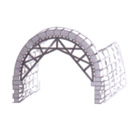
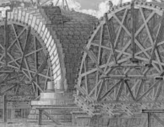
Even a simple semi-circular voussoir arch cannot be built without faux-works or centering because the structure will not stand up until every voussoir is in place. Temporary centering structures were made of wood, and the carpenters often erected, dismantled and re-erected the same centering on different rings of the arch, across the barrel, until each arch was completed. More frequently, an entire arch falsework was constructed of wood. Hutton notes that timber was a significant part of the cost, and that the same profile could only be used if all the arches were the same size. Hence differently sized arches were rare and expensive. It was always known that abutments had to be constructed in solid anchored masonry; frequently ashlar was used and sometimes short wooden piles were driven into the foundation layer in advance of the masonry.
The construction of multi-arched bridges presented particular challenges. Semicircular arches will stand alone if the barrel is sufficiently thick. Each arch can be built separately, and the wooden centering can then be dismantled and moved on to the next arch. Segmental arches with slender piers (less than 1/4 of span) will usually rely on the lateral resistance buttressing from the immediate neighbouring arch. The obvious implication is that false-works are required for the entire structure, all at the same time, to avoid complete collapse. Once completed, however, the advantage of low flat segmental arches lies in reduced height for a given span, so that fewer piers are needed. There is also more flexibility and room for diversity with a slimmer more elegant profile and a clear advantage of less steep gradients on the approach. The disadvantage lies in that very interdependence; if flood-waters engulf these flatter arches they may well all collapse at the same time.
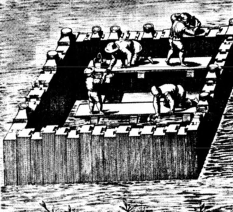
Multi-span bridges had always presented the extra challenge of constructing piers in mid-stream. Gautier discusses this in broad principles. Ruddock (Ref) provides a modern detailed analysis. When possible a rock foundation was chosen, and a site without tidal range was preferred. A small tidal range in shallow water might permit the Roman approach of constructing a wooden cofferdam on the river bed (Old Scots: bulwark. Old French :bâtardeau). In this case, a gin and ram was employed to drive piles into the mud, adjacent to each other, until a full semi-watertight circle was completed, perhaps 50ft. in diameter. Then the central pool was emptied by chains of men with ladders and scoops. A wider tidal range usually required starlings: these were artificial islands. The construction was similar to a cofferdam, but piles were driven into the river bed and a chamber was constructed; rubble was then poured in to the chamber on each receding tide. The stone piers were built on top of the starling. This arrangement was more commonly seen below English bridges and was clearly recorded at Berwick. The French called this an encaissement and filled it with a crude concrete mix (The word ‘pile’ is confusing; the French used it to describe a pier, whereas, in French, a pile is ‘un pieu’.) A more common approach, seen more often in Scotland, and also useful for a significant tidal height, was to sink a large wooden frame or ‘brander' made up of longitudinal planks. This frame would be filled directly with rubble and sunk on the required spot. In this way, a different form of starling was created which had no vertical piles. The French called it a 'crêche’, the English, a‘ grating’. There are reliable records of brander foundations at Ayr, Dee, Perth and Stirling. Hutton’s late 18th-century glossary describes a Caisson, not as a cofferdam as would be expected, but as a wooden boat on which the pier was constructed in ashlar only to be sunk when it reached low-tide level height. This appears to be a later version of a grating.
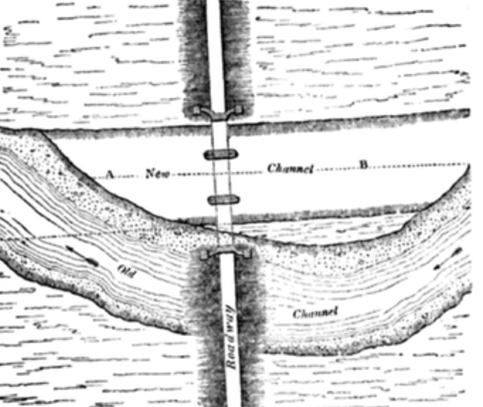
Gautier described one further approach: that of diverting the whole river while foundations were being built. This may have been less of a last resort than one might think: Hughes (Ref) , in 1839, describes a variation suitable for a meandering river on a lowland basin; the bridge would be built on dry land in advance of a permanent diversion of the river, as shown. There are no known examples in Scotland but this may be because of the absence of records. In 1808, Telford partially diverted the River Tay when building the bridge at Dunkeld, although this was more in the nature of a huge cofferdam.
Multi-span bridges need piers with triangular cutwaters, facing the current, to provide the best protection against scouring (undermining of the foundations). In the 15th-century Alberti pointed out that these were just as important on the downstream side. In earlier times, ‘framing and setting’ of short piles overlaid with masonry formed a defence which was installed some yards upstream of the pier. This divided the current and was more disposable and renewable. The single most important element of maintenance was the constant attention to the risk of scouring.
On top of the piers, the centering for all the arches would then be built, and this would be followed by the voussoir arches in solid dressed masonry. If ribs were used these were almost always in ashlar. Puddled clay might be used as a waterproofing over the top (arch-back) of the arch. Sometimes a second order of voussoirs was built, often called a counter-course. The spandrels were last to be constructed with infill rubble to provide a plane for the cobbled surface. It was good practice to keep the centering in place until the spandrels were complete. Parapets were an optional extra, sometimes deliberately omitted; for example, the narrow old packhorse bridges required that nothing should impede the large panniers on each side of the horse.
It is now known that most bridge arches experienced some outward shift (spreading) of the abutments, probably when the centering was removed. This minor settlement caused cracks in the arch in three places, usually at the crown and at both haunches. An arch structure is no less stable because of these hinges but any deterioration leading to a fourth hinge would be unsustainable. This three-hinged state is so common that it can be considered a natural state.
Jean Randolph Perronnet was the most eminent late 18th-century bridge builder, and the architect of the huge segmental Pont de Neuilly in Paris (1783.) He and his contemporaries were very critical of medieval engineering, but their criticism was misplaced and lacked perspective. Many Medieval structures have remained standing for 500 years, and many more were replaced in the 19th century, not because they were at risk, but only because they were too narrow for increasing traffic. Rochester's Medieval bridge on the Medway was so solid that it had to be blown up in order to be dismantled. These old bridges frequently spanned wide, deep, fast-flowing rivers with frequent flooding. Their longevity was largely a function of repair to the foundations and constant attention to starlings and branders to avoid scouring, and regular inspection of abutments which are always at risk of displacement. However, some design features were pivotal to this long-term success: segmental arches with their lower profile have to be built with a very high standard of masonry if they are to survive the years; however, semicircular and Gothic arches create less dependence between arches so that the whole structure can survive the collapse of a single arch; also, they have more height, ensuring that the river banks will burst before water levels reach the crown, an event which is frequently fatal. Many old bridges have flood-arches on dry land which also helps. These design features have been incorporated repeatedly, over 2000 years. That, in itself, is a recommendation.
Today these old masonry arch bridges are often expected to carry modern traffic. Eight of the pre-1600 bridges still remain on the Scottish road network along with a further sixty, which are structurally from before 1750, and still taking traffic. In all cases, the implied live loads are far beyond the expectations of the original builders. Since the 18th century, engineers have attempted to answer questions about the safety of existing bridges and about their carrying capacity. Danyzy’s (Ref) elegant experiments in 1732 identified the hinging failure leading to collapse. Castigliano (Ref) introduced non-linear elastic stress analysis and proposed the middle third rule. Pippard’s (Ref) elastic method in the 1930s was further developed into the MEXE system which has been in general use since the 1940s. Heyman (Ref), in the 1970s, introduced Plastic Theory and Limit Analysis, references which were later deployed extensively in computer programs such as ‘Archie’. Most of these systems are to some degree underpinned by line-of-thrust theory and computations around expected end-point 'hinge' failures of the old arches. This is not the only approach. Recently, the important strengthening role played by the backfill has been identified which has led to the development of some new modelling strategies. Today, 3D non-linear finite element analysis (FEA) has become a respected, computer-assisted, graphic approach to stresses and displacements. It is probably fair to say that despite the crucial importance of arch safety assessment there still exist uncertainties and inconsistencies in this whole area of research.


Page last updated Oct.2020